ツイスト・ペア線のテスト結果 - MicroScanner2
To test twisted pair cables:
- Turn on the tester.
- If the tester is already on and in coaxial test mode, press PORT to switch to twisted pair test mode.
- Connect the tester and wiremap adapter or ID locator to the cabling as shown in Figure below.
The test runs continuously until you change modes or turn the tester off.
注記
You can measure length without connecting a far end adapter; however, an adapter is required for a complete wiremap test.
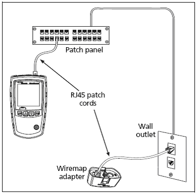
Twisted Pair Test Results
The following examples show typical test results for twisted pair cabling:
Open on Twisted Pair Cabling
Short on Twisted Pair Cabling
Crossed Wires
Crossed Pairs
Split Pair
Open on Twisted Pair Cabling
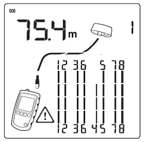
Figure 2 shows an open on wire 4.
The three segments shown for the wire pair length indicate the open is approximately 3/4 the distance to the end of the cabling. The cable length is 75.4 m and is terminated with the wiremap adapter.
注記
If only one wire in a pair is open and a wiremap adapter or remote ID locator is not connected, both wires are shown as open.
The warning icon does not appear if both wires in a pair are open because open pairs are normal for some cabling applications.
Figure 3 displays the distance to the open, use UP ARROW or DOWN ARROW to view the individual result for the wire pair. In this mode, the tester continuously tests only the wire pair you are viewing.
Figure 3 shows examples of these screens.
1. A Short on pair 1, 2 at 29.8 m.
注記
On the individual results screens, shorts are shown only when they are between wires in a pair.
2. Pair 3, 6, is 67.7 m long and is terminated with the wiremap adapter.
3. Open on pair 4, 5 at 48.1 m. the open could be on one or both wires.
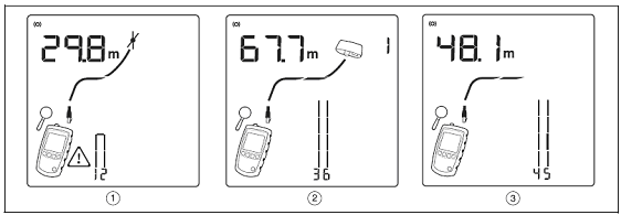
図 3. Results Screens for Individual Wire Pairs
Short on Twisted Pair Cabling
Figure 4 below displays a short between wires 5 and 6. The shorted wires flash to indicate the fault. The cable length is 75.4 m.
注記
When there is a short, the far-end adapter and the mapping of the unshorted wires are not shown.
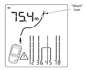
図 4. Short on Twisted Pair Cabling
Crossed Wires
Figure 5 below shows that wires 3 and 4 are crossed. The crossed wires flash to indicate the fault. Cable length is 53.9 m. The cable is shielded and is terminated with the wiremap adapter.
Detection of crossed wires requires a far-end adapter.
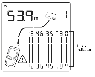
図 5. Crossed Wires
Crossed Pairs
Figure 6 below shows that pairs 1,2 and 3,6 are crossed. The crossed wire pairs flash to indicate the fault. This crossed pair is likely caused by mixing 568A and 568B cabling.
Detection of crossed pairs requires a far-end adapter.
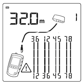
図 6. Crossed Pairs
Split Pair
Figure 7 below shows a split pair on 3, 6 and 4, 5. The split pair flashes to indicate the fault. The cable length is 75.4 m.
In a split pair, continuity from end to end is correct, but is made with wires from different pairs. Split pairs cause excessive crosstalk that interferes with network operation.
Detection of crossed pairs requires a far-end adapter.
注記
Cables with untwisted pairs, such as telephone cords, typically show split pairs due to excessive crosstalk.
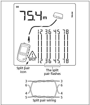
図 7. Split Pair


