ホワイトペーパー
ファイバー試験方法の解説 – 基本への回帰
PDF ダウンロード
このページに記載されていること
Fiber Optic Cable Testing Methods
Fiber optic networks are the backbone of modern telecommunications, providing high-speed data transmission over long distances with minimal loss. The performance and reliability of these networks depend on the quality of the fiber optic cables and the precision of their installation. This is why fiber optic cable testing is critical.
Fiber optic testing ensures the performance and reliability of fiber optic networks. These test procedures assess the physical and functional qualities of fiber optic cables, connectors, and the network as a whole. Key tests include:
- Measuring signal loss
- Verifying the strength and quality of the fiber
- Ensuring compliance with industry standards
Effective fiber testing utilizes advanced tools such as Optical Loss Test Sets (OLTS), Optical Time-Domain Reflectometers (OTDR), and Visual Fault Locators (VFL) to diagnose and correct issues, ensuring optimal network performance. Such a comprehensive approach to fiber optic cable testing safeguards the integrity of data transmission.
Fluke Networks provides comprehensive solutions for fiber optics testing, ensuring your network performs at its optimal level.
What Is Fiber Testing?
Fiber testing evaluates fiber optic cables' performance characteristics and integrity. It verifies the functionality and efficiency of newly installed and existing fiber optic networks. Careful and comprehensive fiber optics testing helps technicians detect issues such as signal loss, interference, and physical damage to the cables, any of which can severely impact network performance.
What Are the Methods of Fiber Testing?
There are several methods of fiber optic cable testing, each serving a specific purpose in assessing the cable's performance and reliability:
- Optical Loss Test Sets (OLTS): This method measures the total light loss in a fiber optic link, simulating the network conditions.
- Optical Time-Domain Reflectometer (OTDR): OTDR testing involves sending pulses of light down the fiber to detect faults, bends, and splice losses by analyzing the light scattered or reflected.
- Visual Fault Locator (VFL): VFLs use a visible light laser to identify breaks and tight bends in the fiber optic cable.
- Fiber Inspection Probes: These devices magnify the end face of a fiber connector, allowing technicians to find dirt, debris, or damage that could impede performance.
What Are the Standards for Fiber Optic Cable Testing?
Industry standards in fiber optic cable testing are crucial for ensuring a fiber optic network’s consistency, reliability, and interoperability. The key standards organizations include:
- TIA/EIA: Sets standards for fiber optic cable system design, installation, and testing in North America.
- IEC: Sets international standards covering various fiber optics testing procedures and parameters.
- ISO: Provides quality management and assurance standards, including those relevant to fiber optic testing.
What Are the Different Types of Fiber Optic Cable Testing?
Fiber optic cable testing can be categorized based on the type of test being conducted:
- End-to-End Testing: Verifies light transmission capability and signal integrity over the entire length of the cable.
- OTDR テスト:Identifies the location and severity of faults within the cable or its connectors.
- Insertion Loss Testing: Measures the loss of signal power resulting from the insertion of a device in a transmission path.
- Return Loss and Reflectance Testing: Assesses the amount of light reflected back toward the source, which can cause signal degradation.
パーマネント・リンクおよびチャネル
パーマネント・リンクの基準面には、敷設されたファイバーの減衰量といずれか一端の2つの接続部が含まれます。リンクには、その他の接続部やスプライスが含まれる場合があります。基準測定または減衰測定に機器コードは使われないため(図 1 参照)、機器コードの減衰量は含まれません。
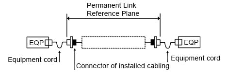
図 1. パーマネント・リンクの基準面
チャネルの基準面には、敷設されたファイバー、接続部、スプライスの減衰量、および機器コードと敷設されたケーブル(ほとんどの場合、パーマネント・リンク)の間の減衰量が含まれます。チャネルには、機器に接続される機器コードの結合部の減衰量は含まれません(図 2 参照)。
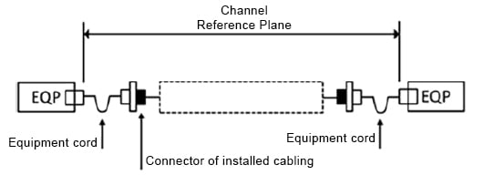
図 2. チャネルの基準面
ケーブル配線構成
ケーブル配線は、以下の構成が考えられます。
- ケーブル両端にアダプターまたはソケット
- ケーブル両端にプラグ
- ケーブルの一端にプラグ、もう一端にアダプターを装着
- 機器コードを使用し、ケーブルの両端にプラグを装着
4 つのケーブル配線構成をテストするのに、5 つの試験方法があります。
- 1コード法
- 2コード法
- 3コード法
- 拡張3コード法
- 機器コードまたはチャネルを用いた方法
1 コード法はパーマネント・リンク試験に用いられ、ランチ・コードをパワー・メーターに直接接続します。パワー・メーターには交換型アダプターが付いています。これは、試験対象のケーブルの両端にアダプターまたはソケットが存在する場合に使われます。1コード法は、測定の不確実性が最も低いため、利用が可能であれば、いつも推奨される方法です。
2 コード法はパーマネント・リンク試験に用いられ、2 つの配線構成に使用できます。1 つは、ケーブルの両端にプラグがある構成です。もう 1 つが、ケーブルの一端にプラグがあり、もう一端にアダプターがある構成です。2コード法は、基本的にケーブルと一端の接続部しか測定しません。
3 コード法では、被測定配線の両接続部の減衰量が除外されます。これは、ピグテールがケーブルの両端にスプライスされ、伝送機器に直接接続される場合に適用できます。この方法は、チャネル試験において、他に実用的な方法がない場合に使用することもできます。
拡張 3 コード法には、被測定配線の両接続部の減衰量が含まれ、リンク測定に使用できます。この方法は、ケーブルの各端のコネクターが異なり、1 コード法の適用が難しい場合に、リンク試験に使用することができます。
機器コード/チャネル試験方法は、ケーブルの両端が機器コードで伝送装置に接続されている場合に使用されます。この方法は、チャネルの減衰測定に使われます。この方法は、3コード法よりも不確実性が低いものの、使い方がより難しくなります。
表 1 では、敷設された光ファイバー・ケーブルの減衰測定の規格、その試験方法、そしてそれらをいつ使用すべきかについて概説しています。表を注意深く見ると、規格間で重複があることが分かります。1 つの規格でしか指定されていない唯一の固有の試験方法は、拡張3コード法です。
| 規格別の試験方法 | |||
|---|---|---|---|
| スタンダード | テスト方法 | 用途 | コメント |
| IEC 61280-4-1 第 2 版を適応した TIA-526-14-C | 1 コード | アダプターが、ケーブル両端のプラグまたはソケットに接続される場合に必要とされるリンクの試験方法。 | |
| 2 コード | ケーブルの一端がアダプターで成端され、もう一端がプラグで成端されるように、ケーブルの両端のコネクターが異なる場合に必要とされるリンクの試験方法。 | ||
| 3 コード | ケーブルの両端にプラグがある場合に必要とされるリンクの試験方法。 | ||
| IEC-61280-4-1 第 3 版(改訂) | 1 コード | アダプターがケーブル両端のプラグまたはソケットに接続される場合に必要とされるリンクの試験方法。 | パワー・メーターのコネクターは、ランチ・コードが接続される被測定配線と互換性があります(パワー・メーターには、交換可型アダプターが付いています)。 |
| 2 コード | ケーブルの両端にプラグが装着されている場合に必要とされるリンクの試験方法。ケーブルの一端がアダプター、もう一端がプラグで成端され、ケーブルの両端のコネクターが異なる場合に必要とされるリンクの試験方法 | ||
| 3 コード | 1コード、3コード、および機器コードの代替となるリンクの試験方法。 | ||
| 機器コード | 機器コードを使用し、ケーブルの両端にプラグが装着されている場合に必要とされるリンクの試験方法 | 1コード法にほぼ類似します。 | |
| IEC 61280-4-2 第 2 版を採用した TIA-526-7 | 1 コード | アダプターがケーブル両端のプラグまたはソケットに接続される場合に必要とされるリンクの試験方法。 | そのまま適用されています。改定ではないため、IEC 61280-4-2 の内容と同じです。 |
| 2 コード | ケーブルの一端がアダプターで成端され、もう一端がプラグで成端されるように、ケーブルの両端のコネクターが異なる場合に必要とされるリンクの試験方法。 | ||
| 3 コード | ケーブルの両端にプラグがある場合に必要とされるリンクの試験方法。 | ||
| TIA-568.3-D | TIA 526-7 および TIA 526-14 で指定される通り。 | チャネル試験には、ISO/IEC テスト規格ではなく、IEC 規格により定義される 3コード法を使用すべきです。 | マルチモードとシングルモードのいずれのリンクにも 1 コード法が推奨されます。 |
| ISO/IEC 14763-3、第 2 版 | 1 コード | 試験対象のケーブルがパワー・メーターと同じインターフェイスの場合のリンクの減衰量。パーマネント・リンクの測定。 | 改訂中 |
| 拡張3コード | 試験対象のケーブルの両端に異なるコネクターが使用されている場合のリンクの減衰量。パーマネント・リンクの測定。 | ||
| チャネル | 機器コードを使用したチャネルの減衰量。機器(トランシーバ)の接続部は除外。チャネルの測定。 | ||
| ARINC 805 | 1コード(マルチモードおよびシングルモード) | 必須の試験方法 | TIA-526-7 (SM) および TIA-526-14 (MM) に基づきます |
パーマネント・リンク試験には、被測定配線の各端の両接続部の減衰量が含まれます。チャネル試験には、機器コードとトランシーバー間の接続部の減衰量は含まれません。
1 コード法
a. ランチ・コードを使用して、光源とパワー・メーターとの間に基準を設けます(図 3 参照)。
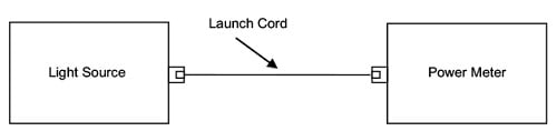
図 3. 基準の設定
a. パワー・メーターにテイル・コードを接続します。
b. ランチ・コードとテイル・コードを試験対象のケーブルに接続します(図 4 参照)。
c. 測定を行い、基準測定の結果と比較します
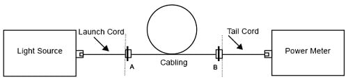
図 4. ケーブル、A 接続部、B 接続部の減衰量の測定
2 コード法
a. ランチ・コードとテイル・コードを使用して、光源とパワー・メーターとの間に基準を設けます(図 5 参照)。
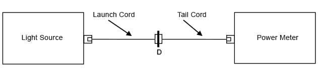
図 5. 基準の設定
b. 測定を行い、基準測定の結果と比較します(図 6a および 6b 参照)。
c. ケース 2 では、アダプター・コードがランチ・コードの一部となります(図 6b 参照)。
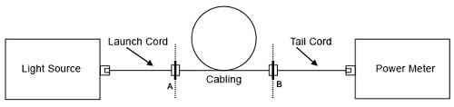
図 6a. ケース 1 の減衰測定(プラグ-アダプターとケーブル両端のプラグ)
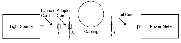
図 6b. ケース 2 の減衰測定(ケーブル両端にソケット付き)
3 コード法
a. ランチ・コード、代替コード、およびテイル・コードを使用して、光源とパワー・メーターとの間に基準を設けます(図 7 参照)。
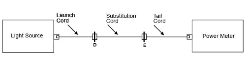
図 7. 基準の設定
a. 代替コードを試験対象のケーブルに置き換えます。
b. 測定を行い、基準測定の結果と比較します(図 8 参照)。
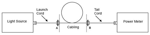
図 8. 減衰測定
拡張 3 コード法
a. ランチ・コードを使用して、光源とパワー・メーターとの間に基準を設けます(図 9 参照)。
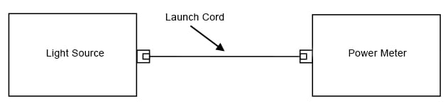
図 9. 1コード法を用いて基準設定
a. パワー・メーターにテイル・コードを接続し、ランチ・コードとテイル・コードの間に代替コードを挿入して、シングルモードで 0.4 dB などの損失が低い接続部を確認します(図 10 参照)。
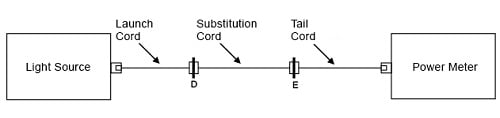
図 10. 低損失の接続部のチェック
a. 代替コードを試験対象のケーブルに置き換えます。
b. ケーブル配線の減衰量を測定して、基準測定の結果と比較します(図 11 参照)。
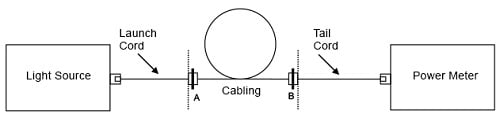
図 11. 減衰測定
機器コード/チャネル試験法
a. ランチ・コードと光源に接続された 1 つめの機器コードを使用して、基準を設けます(図 12 参照)。
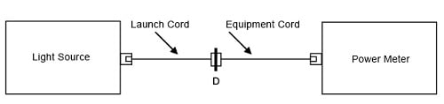
図 12. 基準の設定
a. 2 つめの機器コードをパワー・メーターに接続します。
b. ケーブルに機器コードを接続して、減衰量を測定します(図 13 参照)。
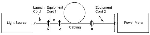
図 13. 減衰測定
概要
パーマネント・リンクとチャネルの違いを理解することは難しいかもしれません。また、どの試験方法を適用すべきか、特にハイブリッド構成において迷うかもしれません。これらのハイブリッド構成は確かに存在するため、これをテストする方法を把握しておくことは、敷設業者にとって利点となります。試験の規格は数多く存在するものの、異なる規格でも試験方法が重複する場合があります。表 1 では、各種規格と試験方法、そしてケーブル配線構成によってどの試験方法を適用すべきかを概説しています。他にも試験方法はありますが、フルーク・ネットワークスはどの試験にも1コード法をお勧めしています。
Learn more about fiber optic testers, tools, and troubleshooting on our Fiber Optic Testers page.


