反射減衰量の測定と試験 - DTX CableAnalyzer
The impact of incorrect characteristic impedance is more accurately measured and represented by the quantity return loss.
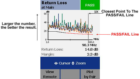
Return Loss (RL) is a measure of all reflections that are caused by the impedance mismatches at all locations along the link and is expressed in decibel (dB). is of particular concern in the implementation of Gigabit Ethernet (1000BASE-T)
The value of impedances at the ends of the link must be equal to the characteristic impedance of the link. Frequently, this impedance is imbedded in the interface of equipment to be connected to the LAN. A good match between characteristic impedance and termination resistance in the equipment provides for a good transfer of power to and from the link and minimizes reflections. The return loss measurement varies significantly with frequency. One source of return loss is due to (small) variations in the value of the characteristic impedance along the cable. The property Structural (SRL) summarizes the uniformity in cable construction. SRL is to be measured and controlled during the cable manufacturing process. Another source is caused by reflections from inside the installed link, mainly from connectors. The characteristic impedance of links tends to vary from higher values at low frequencies to lower values at the higher frequencies.

結果の解釈
All standards define the formulae to calculate the allowable return loss for each cabling link model (Channel and Permanent Link) over the frequency range.

You will note that part of the limit is grey. Any measurements made in this frequency range are ignored under something called the 3 dB rule. Any measurements are ignored if insertion loss is less than 3 dB. On short links, the entire limit line can be grey, since insertion loss never reaches 3 dB. In this case, the return loss measurement is recorded as Information Only.
トラブルシューティングの推奨事項
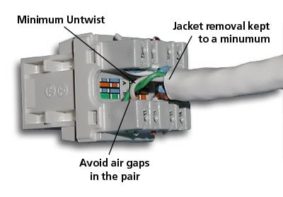
Installation practices are more important on Category 5e and 6 than they were for Category 5. Additional unnecessary untwist in terminations can add several dB of return loss in some cases. Below is an example of a correctly terminated connector. Take note of the minimum jacket removal and twists being maintained

Be sure to apply a high level of care when installing cabling that requires return loss qualification.


