Diagnosing OTDR Test Failures - DTX Compact OTDR Module
- There is one or more dirty or damaged connections in the cabling. Check the OTDR trace or event table for high-loss reflective events.
- The wrong fiber type is selected on the OTDR tab in Setup.
- A patch cord, launch fiber, or fiber segment has the wrong core size, backscatter coefficient, or mode field diameter. If the patch cords and launch fiber are the correct type, check the OTDR trace for mismatched cable in the cabling.
- The cabling has a bad fusion or mechanical splice or a sharp bend. Use the OTDR trace or event table to locate these faults.
注記
OVERALL LOSS may show a WARNING if the first or last event is hidden. If launch compensation was used, a WARNING occurs if the launch event is hidden, or if the event after the receive event is hidden.
Largest Event fails:
- The event is a dirty or damaged connector. Check the OTDR trace or event table for high-loss reflective events.
- A patch cord, launch fiber, or fiber segment has the wrong core size, backscatter coefficient, or mode field diameter. If the patch cords and launch fiber are the correct type, check the OTDR trace for mismatched cable in the cabling.
- The event is a bad fusion or mechanical splice or a sharp bend. Use the OTDR trace or event table to locate these faults.
Fiber Length fails, a known length of cabling measures too long or too short, or the distance to an event is wrong:
- The fiber is broken or there is an open connection where the trace shows the fiber end.
- The wrong fiber type is selected on the Cable tab in Setup.
- The index of refraction needs adjustment. Change n on the Cable tab in Setup.
- The wrong test limit is selected on the OTDR tab in Setup.
An event shows a FAIL result, but the event does not exceed any limit:
The segment before the event exceeds a limit. To see results for the segment, F3 View Details from the Event Table or the OTDR Results screen.
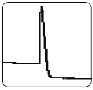
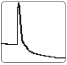
Large reflective event with high loss (top) or excessive tailing (bottom). May be identified as an end event though it occurs before the end of the cabling. See Figure 1 and 2 below.
May be caused by the following:
- A dirty, scratched, cracked, misaligned, or unseated connector. Misaligned or unseated connectors can also cause large reflections that produce ghosts. Bad connectors should be cleaned, re-polished, or replaced.
- A good connector with a sharp bend or crack within its deadzone. If the cable is tightly bent the tester may indicate a break, especially at longer wavelengths or in Manual OTDR mode with smaller resolution settings. Use a visual fault locator to precisely locate the fault.
- A crack in the fiber. Use a visual fault locator to precisely locate the fault.
- A connection between mismatched fibers (different backscatter coefficients, core sizes, numerical apertures, or other parameters). The top example could be caused by a larger core (on the left) connected to a smaller core.
|
|
|
May be caused by very sharp bend, a crack, or a mechanical splice with high loss. If the event is a bend, it may show higher loss at a longer wavelength. Use a visual fault locator to verify the problem. Bad mechanical splices should be reworked.
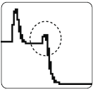
図 3
Large reflective event with gain (a “gainer"). 図 4 を参照.
A connector between mismatched fibers (different backscatter coefficients, core sizes, numerical apertures, or other parameters). This example shows a smaller core size connected to a larger core size. Testing from the other end would show a large reflective event with more loss than a connector should have.
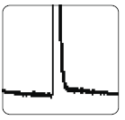
図 4
Ghost after the cabling end. 図 5 を参照.
These are not listed in the event table and generally do not indicate a fault in the cabling.
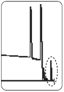
図 5
Ghosts in the middle of the cabling. 図 6 を参照.
Ghosts occurring in the middle of the cabling are listed in the event table, along with the source of the ghosts. These can be caused by a dirty connector, a highly-reflective connector or a connector that is not seated properly. A poorly-seated connector usually shows significant loss, as shown in the example. A connector with the wrong type of polish can also cause strong reflections that result in ghosts.
Ghosts caused by hidden events may not be identified as ghosts in the event table.
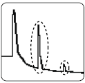
図 6
Tip: On traces with multiple ghosts, only the first ghost may be identified in the event table. You can usually determine that other reflections are ghosts because they occur at multiples of distances to connectors and they show almost no loss. Multiple ghosts from the same source are spaced equally apart.

