ランチ・ファイバー補正の設定 - DTX Compact OTDR モジュール
About Launch and Receive Fibers
Launch and receive fibers let the tester measure the loss and reflectance of the first and last connectors in the cabling. Without launch and receive fibers, no backscatter is available before the first connector and after the last, so the tester cannot measure the connectors’ characteristics. If the first or last connection in the cabling is bad, and you do not use launch and receive fibers, the OTDR test may pass because it does not include measurements from the bad connection.
Overall Loss and Length include the loss and length of the launch and receive fibers, unless launch compensation was enabled during the test.
Fluke Networks recommends that you use launch and receive fibers. You should also use launch compensation to remove the effects of these fibers from the OTDR measurements.
注記
Do not use hybrid patch cords to connect to the cabling under test. Connect the launch and receive fibers directly to the cabling under test, using a launch fiber with the appropriate connectors. This provides the best view of the connectors at the ends of the cabling. Hybrid launch fibers with various connector styles are available from Fluke Networks.
Setting the Launch Fiber Compensation
- Turn the rotary switch to SETUP, select Fiber OTDR; then select the OTDR Port to be used (multimode or singlemode).
-
Turn the rotary switch to SPECIAL FUNCTIONS; then select Set Launch Fiber Compensation. -
On the Set Launch Method screen highlight the type of compensation you want to do. (Figure 1)
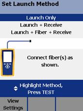
図 1. Set Launch Compensation Method
-
Clean the tester's OTDR port and launch fiber connectors.
- Connect the fibers to the tester's OTDR port as shown on the screen and in Figures 2, 3 or 4 then press TEST.
The tester attempts to identify the launch and receive fiber ends based on the launch method you selected, and displays the results in the Event Table (Figure 5).
In the Event Table, the launch event is shown asthe receive event is shown as
, and thelaunch/receive event is shown as
.
- To see where the markers are set on the trace, press F1 View Trace.
-
Press SAVE; then press F2 OK. Launch Compensation is automatically enabled in Setup.
Figure 6 shows an example of an OTDR trace with launch and receive markers enabled.

図 2. Launch Only Compensation Connections
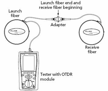
図 3. Launch + Receive Compensation Connections
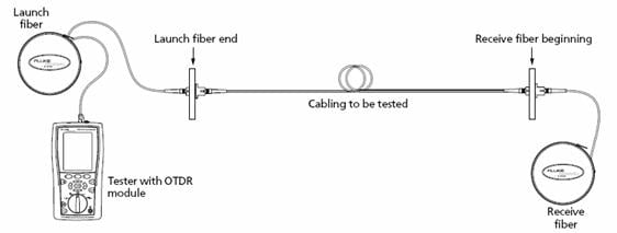
図 4. Launch + Fiber + Receive Compensation Connections

図 5. Launch/Receive Events in the Event Table
- Launch/Receive event, indicated by the launch/receive event icon shown for Launch + Receive compensation.
-
Press F1 View Trace to see the trace used for the launch compensation settings. -
If the launch or receive event is misidentified in the event table, use UP ARROW / DOWN ARROW to select the correct event, then use the F2 and F3 softkeys to remove or move the launch or receive event assignments.
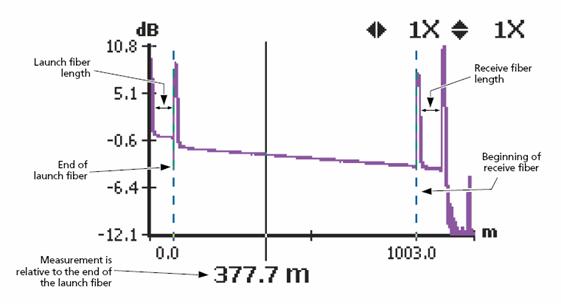
図 6. OTDR Trace with Launch Compensation Enabled


