Angled Physical Contact Connectors (APC) - OptiFiber
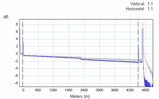
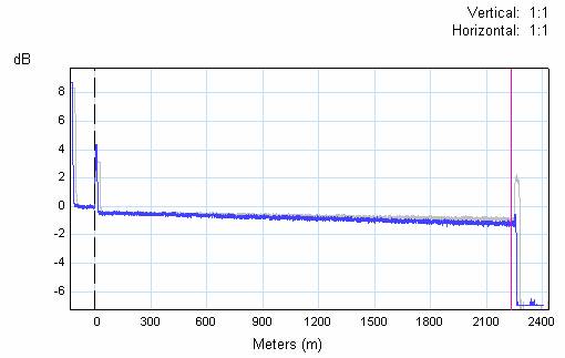
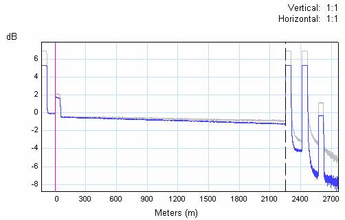
| The most common types of fiber connectors are PC and UPC (ultra physical contact). With UPC, the fiber ends are more rounded than the PC finish giving greater contact between the glass surfaces. This in turn reduces the amount of light reflected back. This is why Fluke Networks uses UPC in all of its test equipment. We are starting to see APC (angled physical contact) connectors in the local area network. These connectors have typically been reserved for long haul telecoms. In this environment, high power lasers are used which are very sensitive to reflections. Severe reflections can destroy the laser. So what is different about the APC? A slight angle is introduced on the curved ends. Any reflected light is directed at an angle to the axis of the core. These reflections are normally sent out of the core through the cladding. The result of this is very small return losses. Because of these characteristics, the OptiFiber (All OTDRs) will show APC connections as a splice / non reflective loss. Example 1: APC connectors in middle of the fiber run  The OTDR trace from the OptiFiber showed this event as a non reflective loss, similar to an event caused by a splice or a bend. Example 2: APC Connector at end of fiber run  In this particular example, the APC connector at the end of the fiber run produced very little reflection. In some cases the OptiFiber might show this as a Warning and state that the Receive Event Not Found. Example 3: APC and UPC mated connection  When an APC connector is matched with a UPC connector, the anti-reflectance characteristics are nullified. In this particular example, this APC/UPC connection causes such bad reflections that the trace shows echoes of the APC/UPC connection. When using a device such as the OptiFiber to test APCs, it is important to note that:
|
詳細:
- OTDR


